


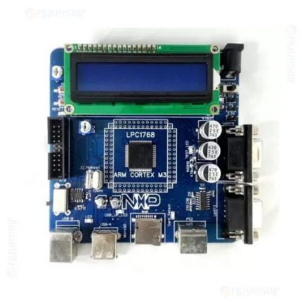
Description
BlueBoard-LPC214X is an evaluation board for LPC2148 ARM7TMDI based microcontroller. The LPC2148 microcontroller has 512KB of internal flash and 32+8K RAM. Following are the salient features of the board. > Dimensions: 112 X 122 mm2 > Two layer PCB (FR-4 material) > Power supply: DC 9V with power LED > On-board linear regulators generate +3.3V/500mA and +5v/500mA from power supply. > USB connector (as alternate power source). Connectors: Extension headers for all microcontroller pins. RS232 connectors (2). PS/2 connector. JTAG connector. SD/MMC connector. USB B-type connector with Link-LED. > Other Peripherals: > 512Kb I2C based EEPROM Audio power amplifier. > 2 line X 16 character LCD with back light control. > Configurable for manual and automatic program download (ISP) via serial port. 8 controllable LEDs on SPI using 74HC595. > User Interrupt, ADC, Buzzer, RTC. 2: System Requirements: > Windows XP & Win 7 > Serial or Parallel port > USB port 3: Starting off & connecting the hardware: After unpacking the LPC2148 board connect a DC supply of 9V/1A to the DC jack to power the board. The LPC2148 board can also be powered through USB. 4: Programming LPC2148 Board: LPC2148 Board can be programmed through serial port UART â0â using âLPC2000 flash utility V2.2.2â is a freeware windows utility used to download the hex file format onto the LPC2148 Board. If your PC does not have a serial port; use a USB to serial converter to download the hex file. > Programming LPC2148 Board through ISP. The LPC2148 Board can be programmed through ISP in two modes: 1. Auto Mode 2. Manual Mode 1. Auto Mode: To program in Auto mode you need a full serial cable with DTR & RTS. (Recommended not to use Auto Mode). 2. Manual Mode: To program in Manual mode you need a half serial cable (which just has TX, RX and GND wire connected). And connect the half serial cable to UART0 and power the board. (Recommended mode) > Open LPC2000 Flash Utility V2.2.2 > Browse File name and Select the hex file to be downloaded. > Select Device as LPC2148 > Set XTL Freq [KHz] to 12000 > Blank Check: Entire Device > Select the appropriate com port (See your âdevice managerâ to find out the com port number) > Select the Baud Rate in between 9600 and 38400 > Uncheck âUse DTR/RTS for Reset and Boot Loader Selectionâ > Click on Read Device ID. To make the board enter programming mode > Hold down ISP and RESET Buttons, then release RESET first and finally ISP. > The controller enters the bootloader mode. > It will display as âRead device ID Successfulâ. > Click on the Upload to Flash Button. > Program uploaded successfully. > Click the Rest Button on the Board. Thatâs it, your hex file is on the board.
Specifications
|
General
| brand |
|
| Model Number |
|
| Type |
|
| Minimum Age |
|
| ROHS Complaint |
|
| Material |
|
Additional Features
| Other Features |
|
Dimensions
| Width |
|
| Height |
|
| Other Dimensions |
|
| Weight |
|
Power Features
| Battery Type |
|
| No Of Batteries |
|
| Battery Size |
|
| Power Source |
|
| Power Consumption |
|
| Other Power Features |
|


Reviews
There are no reviews yet.